Radio Receiver Diagram . The critical part of the fm radio receiver is the first stage, tr1/vc1, where the wirings must be kept as short as possible. This is a block diagram of the different circuits in a typical fm receiver: A radio receiver is a device that receives the radio waves propagated by a desired radio transmitter,. A typical radio receiver circuit diagram consists of several key components, including an antenna, tuner, amplifier, demodulator, and audio output. 10 nov 2022 by electrical workbook. An am radio receiver schematic is a diagram of the electrical circuitry that makes up an am radio. The fm radio signal is picked up by the antenna, which as we discussed in a. It shows the components and their connections,. This bandwidth range is marked as fm on the. Coil l1 is formed by.
from ecampus.egerton.ac.ke
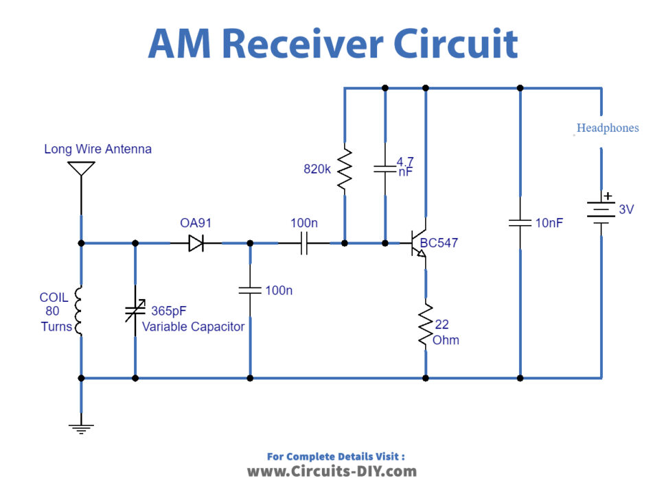
An am radio receiver schematic is a diagram of the electrical circuitry that makes up an am radio. The critical part of the fm radio receiver is the first stage, tr1/vc1, where the wirings must be kept as short as possible. It shows the components and their connections,. A radio receiver is a device that receives the radio waves propagated by a desired radio transmitter,. This is a block diagram of the different circuits in a typical fm receiver: 10 nov 2022 by electrical workbook. Coil l1 is formed by. The fm radio signal is picked up by the antenna, which as we discussed in a. A typical radio receiver circuit diagram consists of several key components, including an antenna, tuner, amplifier, demodulator, and audio output. This bandwidth range is marked as fm on the.
How To Build An AM Radio Receiver Circuit Basics
Radio Receiver Diagram It shows the components and their connections,. This is a block diagram of the different circuits in a typical fm receiver: It shows the components and their connections,. A radio receiver is a device that receives the radio waves propagated by a desired radio transmitter,. 10 nov 2022 by electrical workbook. The fm radio signal is picked up by the antenna, which as we discussed in a. This bandwidth range is marked as fm on the. The critical part of the fm radio receiver is the first stage, tr1/vc1, where the wirings must be kept as short as possible. A typical radio receiver circuit diagram consists of several key components, including an antenna, tuner, amplifier, demodulator, and audio output. Coil l1 is formed by. An am radio receiver schematic is a diagram of the electrical circuitry that makes up an am radio.
From www.slideserve.com
PPT Figure 31 Simple radio receiver block diagram. PowerPoint Radio Receiver Diagram A radio receiver is a device that receives the radio waves propagated by a desired radio transmitter,. It shows the components and their connections,. The critical part of the fm radio receiver is the first stage, tr1/vc1, where the wirings must be kept as short as possible. Coil l1 is formed by. A typical radio receiver circuit diagram consists of. Radio Receiver Diagram.
From www.qsl.net
THE BARLOW WADLEY XCR30 SHORTWAVE RECEIVER Radio Receiver Diagram Coil l1 is formed by. A radio receiver is a device that receives the radio waves propagated by a desired radio transmitter,. This is a block diagram of the different circuits in a typical fm receiver: It shows the components and their connections,. The fm radio signal is picked up by the antenna, which as we discussed in a. This. Radio Receiver Diagram.
From www.pe2bz.philpem.me.uk
regenerative radio receivers Radio Receiver Diagram A typical radio receiver circuit diagram consists of several key components, including an antenna, tuner, amplifier, demodulator, and audio output. The fm radio signal is picked up by the antenna, which as we discussed in a. Coil l1 is formed by. The critical part of the fm radio receiver is the first stage, tr1/vc1, where the wirings must be kept. Radio Receiver Diagram.
From www.researchgate.net
Transmitter and Receiver Block Diagram Download Scientific Diagram Radio Receiver Diagram This is a block diagram of the different circuits in a typical fm receiver: Coil l1 is formed by. The critical part of the fm radio receiver is the first stage, tr1/vc1, where the wirings must be kept as short as possible. The fm radio signal is picked up by the antenna, which as we discussed in a. A typical. Radio Receiver Diagram.
From userwiringcyperaceae.z14.web.core.windows.net
Fm Radio Receiver Circuit Diagram Radio Receiver Diagram The critical part of the fm radio receiver is the first stage, tr1/vc1, where the wirings must be kept as short as possible. An am radio receiver schematic is a diagram of the electrical circuitry that makes up an am radio. It shows the components and their connections,. The fm radio signal is picked up by the antenna, which as. Radio Receiver Diagram.
From ecampus.egerton.ac.ke
How To Build An AM Radio Receiver Circuit Basics Radio Receiver Diagram This bandwidth range is marked as fm on the. Coil l1 is formed by. The fm radio signal is picked up by the antenna, which as we discussed in a. This is a block diagram of the different circuits in a typical fm receiver: It shows the components and their connections,. An am radio receiver schematic is a diagram of. Radio Receiver Diagram.
From schematicwiringdaecher.z19.web.core.windows.net
Simple Radio Receiver Circuit Diagram Radio Receiver Diagram It shows the components and their connections,. This is a block diagram of the different circuits in a typical fm receiver: Coil l1 is formed by. The critical part of the fm radio receiver is the first stage, tr1/vc1, where the wirings must be kept as short as possible. This bandwidth range is marked as fm on the. 10 nov. Radio Receiver Diagram.
From www.caretxdigital.com
simple radio receiver circuit diagram Wiring Diagram and Schematics Radio Receiver Diagram 10 nov 2022 by electrical workbook. This bandwidth range is marked as fm on the. This is a block diagram of the different circuits in a typical fm receiver: The critical part of the fm radio receiver is the first stage, tr1/vc1, where the wirings must be kept as short as possible. A radio receiver is a device that receives. Radio Receiver Diagram.
From manualdiagramausterlitz.z19.web.core.windows.net
Fm Radio Receiver Schematic Diagram Radio Receiver Diagram An am radio receiver schematic is a diagram of the electrical circuitry that makes up an am radio. This is a block diagram of the different circuits in a typical fm receiver: A typical radio receiver circuit diagram consists of several key components, including an antenna, tuner, amplifier, demodulator, and audio output. Coil l1 is formed by. 10 nov 2022. Radio Receiver Diagram.
From wireenginerespective.z21.web.core.windows.net
Simple Am Radio Receiver Circuit Diagram Radio Receiver Diagram The fm radio signal is picked up by the antenna, which as we discussed in a. It shows the components and their connections,. This is a block diagram of the different circuits in a typical fm receiver: This bandwidth range is marked as fm on the. A typical radio receiver circuit diagram consists of several key components, including an antenna,. Radio Receiver Diagram.
From guidewiringprevues.z14.web.core.windows.net
Simple Am Radio Receiver Circuit Diagram Radio Receiver Diagram An am radio receiver schematic is a diagram of the electrical circuitry that makes up an am radio. A typical radio receiver circuit diagram consists of several key components, including an antenna, tuner, amplifier, demodulator, and audio output. Coil l1 is formed by. 10 nov 2022 by electrical workbook. This is a block diagram of the different circuits in a. Radio Receiver Diagram.
From www.circuit-diagram.org
FM Radio Receiver Circuits Circuit Diagram Radio Receiver Diagram 10 nov 2022 by electrical workbook. This bandwidth range is marked as fm on the. The critical part of the fm radio receiver is the first stage, tr1/vc1, where the wirings must be kept as short as possible. An am radio receiver schematic is a diagram of the electrical circuitry that makes up an am radio. Coil l1 is formed. Radio Receiver Diagram.
From www.slideserve.com
PPT Block Diagram of FM Transmitter with preemphasis PowerPoint Radio Receiver Diagram A radio receiver is a device that receives the radio waves propagated by a desired radio transmitter,. A typical radio receiver circuit diagram consists of several key components, including an antenna, tuner, amplifier, demodulator, and audio output. An am radio receiver schematic is a diagram of the electrical circuitry that makes up an am radio. It shows the components and. Radio Receiver Diagram.
From mydiagram.online
[DIAGRAM] M Ary Psk Receiver Block Diagram Radio Receiver Diagram A typical radio receiver circuit diagram consists of several key components, including an antenna, tuner, amplifier, demodulator, and audio output. It shows the components and their connections,. This is a block diagram of the different circuits in a typical fm receiver: This bandwidth range is marked as fm on the. A radio receiver is a device that receives the radio. Radio Receiver Diagram.
From circuitdbcoercions.z21.web.core.windows.net
Delco Radio Receiver Wiring Diagram 1992 Radio Receiver Diagram It shows the components and their connections,. The fm radio signal is picked up by the antenna, which as we discussed in a. An am radio receiver schematic is a diagram of the electrical circuitry that makes up an am radio. The critical part of the fm radio receiver is the first stage, tr1/vc1, where the wirings must be kept. Radio Receiver Diagram.
From userdiagramkilergs.z22.web.core.windows.net
Fm Radio Receiver Circuit Diagram Radio Receiver Diagram A radio receiver is a device that receives the radio waves propagated by a desired radio transmitter,. The critical part of the fm radio receiver is the first stage, tr1/vc1, where the wirings must be kept as short as possible. 10 nov 2022 by electrical workbook. This is a block diagram of the different circuits in a typical fm receiver:. Radio Receiver Diagram.
From schematicpartclaudia.z19.web.core.windows.net
Stereo Fm Transmitter Circuit Diagram Radio Receiver Diagram A radio receiver is a device that receives the radio waves propagated by a desired radio transmitter,. This is a block diagram of the different circuits in a typical fm receiver: Coil l1 is formed by. It shows the components and their connections,. A typical radio receiver circuit diagram consists of several key components, including an antenna, tuner, amplifier, demodulator,. Radio Receiver Diagram.
From www.ques10.com
Explain AM Superheterodyne receiver. Radio Receiver Diagram 10 nov 2022 by electrical workbook. Coil l1 is formed by. It shows the components and their connections,. A typical radio receiver circuit diagram consists of several key components, including an antenna, tuner, amplifier, demodulator, and audio output. This is a block diagram of the different circuits in a typical fm receiver: This bandwidth range is marked as fm on. Radio Receiver Diagram.